SDC Commands
The following subset of SDC syntax is supported by VPR.
create_clock
Creates a netlist or virtual clock.
Assigns a desired period (in nanoseconds) and waveform to one or more clocks in the netlist (if the –name option is omitted) or to a single virtual clock (used to constrain input and outputs to a clock external to the design).
Netlist clocks can be referred to using regular expressions, while the virtual clock name is taken as-is.
Example Usage:
# Create a netlist clock
create_clock -period <float> <netlist clock list or regexes>

# Create a virtual clock
create_clock -period <float> -name <virtual clock name>

# Create a netlist clock with custom waveform/duty-cycle
create_clock -period <float> -waveform {rising_edge falling_edge} <netlist clock list or regexes>

# Add a second clock on the same pin (e.g. physically-exclusive clocks driven by a board-level mux).
# Only one clock physically enters the chip at a time, so use -physically_exclusive.
create_clock -period <float> -name clk_a <pin>
create_clock -period <float> -name clk_b -add <pin>
set_clock_groups -physically_exclusive -group {clk_a} -group {clk_b}

# Add a second clock on the output of an internal clock mux inside the FPGA design.
# Both clock trees are physically present in the fabric simultaneously (the mux just
# selects which one propagates), so use -logically_exclusive.
create_clock -period <float> -name clk_fast <mux_out_pin>
create_clock -period <float> -name clk_slow -add <mux_out_pin>
set_clock_groups -logically_exclusive -group {clk_fast} -group {clk_slow}
Omitting the waveform creates a clock with a rising edge at 0 and a falling edge at the half period, and is equivalent to using -waveform {0 <period/2>}.
Non-50% duty cycles are supported but behave no differently than 50% duty cycles, since falling edges are not used in analysis.
If a virtual clock is assigned using a create_clock command, it must be referenced elsewhere in a set_input_delay or set_output_delay constraint.
- create_clock
- -period <float>
Specifies the clock period.
Required: Yes
- -waveform {<float> <float>}
Overrides the default clock waveform.
The first value indicates the time the clock rises, the second the time the clock falls.
Required: No
Default: 50% duty cycle (i.e.
-waveform {0 <period/2>}).
- -name <string>
Specifies the clock name. Required when defining a virtual clock or when using
-add.Required: No
- -add
Adds a new clock definition on a source pin that already has a clock. This is used to model multiple clocks that can appear on the same pin at different times (e.g. a board-level mux selecting among several clock sources).
-nameis required when using-addto distinguish each clock on the same source.-adddoes not implicitly make the clocks asynchronous or exclusive. Useset_clock_groupsto specify the relationship between clocks that share a source pin.Required: No
- <netlist clock list or regexes>
Creates a netlist clock
Required: No
Note
One of -name or <netlist clock list or regexes> must be specified.
Warning
If a netlist clock is not specified with a create_clock command, paths to and from that clock domain will not be analysed.
create_generated_clock
Defines a derived clock based on an existing source clock.
Generated clocks are used to describe clock signals created by internal design logic (such as clock dividers or multipliers). The frequency of the generated clock is defined by scaling the frequency of a master clock.
A common use-case for generated clocks is PLLs (Phase-Locked Loops). An architecture may contain PLL primitives which take in a source clock and produce a generated clock at a different frequency. The create_generated_clock command informs the timing analyzer of the relationship between the PLL’s output clock and its source clock.
Example Usage:
# Create a master clock to generate the clocks relative to.
create_clock -period 6.0 -name master_clk [get_pins {div_clk.clk[0]}]

# Create a clock that is half the frequency of 'master_clk'
create_generated_clock -source [get_pins {div_clk.clk[0]}] -divide_by 2 [get_pins {div_clk.Q[0]}]

# Create a clock that is triple the frequency of 'master_clk' with a custom name
create_generated_clock -name fast_clk -source [get_pins {pll.ref[0]}] -multiply_by 3 [get_pins {pll.out[0]}]

# Create a divided clock that is phase-inverted relative to the source
create_generated_clock -source [get_pins {div_clk.clk[0]}] -divide_by 2 -invert [get_pins {div_clk.Q[0]}]

# Create a multiplied clock with a 30% duty cycle
create_generated_clock -source [get_ports clk] -multiply_by 3 -duty_cycle 30 [get_ports clk2]

# Create a divide-by-2 clock using explicit master clock edge indices.
# Edge 1 (1st rise) -> 0 ns, edge 3 (2nd rise) -> 6 ns, edge 5 (3rd rise) -> 12 ns.
# Generated clock: rise=0 ns, fall=6 ns, period=12 ns. Equivalent to -divide_by 2.
create_generated_clock -source [get_ports clk] -edges {1 3 5} [get_ports clk2]

# Create a clock with a non-standard 25% duty cycle using mixed edge indices.
# -edges {1 2 5} cannot be expressed with -divide_by or -multiply_by alone.
# Edge 1 (1st rise) -> 0 ns, edge 2 (1st fall) -> 3 ns, edge 5 (3rd rise) -> 12 ns.
# Generated clock: rise=0 ns, fall=3 ns, period=12 ns.
create_generated_clock -source [get_ports clk] -edges {1 2 5} [get_ports clk2]

# Apply per-edge time shifts to the -edges waveform.
# Shifts each edge time by 0.5 ns, phase-offsetting the generated clock.
# Generated clock: rise=0.5 ns, fall=6.5 ns, period=12 ns.
create_generated_clock -source [get_ports clk] -edges {1 3 5} -edge_shift {0.5 0.5 0.5} [get_ports clk2]

# Use an asymmetric -edge_shift to independently nudge the fall edge.
# Edge 1 -> 0 ns, edge 3 -> 6-1=5 ns, edge 5 -> 12 ns.
# Generated clock: rise=0 ns, fall=5 ns, period=12 ns (~41.7% duty cycle).
create_generated_clock -source [get_ports clk] -edges {1 3 5} -edge_shift {0.0 -1.0 0.0} [get_ports clk2]

# Create a phase-shifted copy of the master clock on a second port.
# -phase 90 shifts all edges by 90/360 * 10 ns = 2.5 ns. Period is unchanged.
# Generated clock: rise=2.5 ns, fall=7.5 ns, period=10 ns.
create_clock -period 10.0 -name master_clk [get_ports {clk}]
create_generated_clock -source [get_ports {clk}] -phase 90 [get_ports {clk2}]

# Create a divided clock with a fixed time offset applied to the waveform.
# -divide_by 2 gives period=12 ns; -offset 3.0 shifts both edges by 3 ns.
# Generated clock: rise=3 ns, fall=9 ns, period=12 ns.
create_clock -period 6.0 -name master_clk [get_ports {clk}]
create_generated_clock -source [get_ports {clk}] -divide_by 2 -offset 3.0 [get_ports {clk2}]

# Add a second generated clock on the same target pin, each derived from a different
# master clock. The source pin carries two physically-exclusive clocks (clk_a and clk_b)
# defined with create_clock -add. -master_clock selects which one each generated clock
# is derived from. -add on the second create_generated_clock allows both to coexist on
# the same target pin.
create_clock -period 5.0 -name clk_a [get_pins {div_clk.clk[0]}]
create_clock -period 10.0 -name clk_b -add [get_pins {div_clk.clk[0]}]
set_clock_groups -physically_exclusive -group {clk_a} -group {clk_b}
create_generated_clock -source [get_pins {div_clk.clk[0]}] -master_clock clk_a -divide_by 2 -name gen_clk_a [get_pins {div_clk.Q[0]}]
create_generated_clock -source [get_pins {div_clk.clk[0]}] -master_clock clk_b -divide_by 2 -name gen_clk_b -add [get_pins {div_clk.Q[0]}]
set_clock_groups -physically_exclusive -group {gen_clk_a} -group {gen_clk_b}
- create_generated_clock
- -name <string>
Specifies the name of the generated clock.
Required: No (Required if no targets are specified, or when using
-add)
- -source <pin>
Specifies the pin or port in the design that serves as the master source for the generated clock.
Required: Yes
- -divide_by <integer>
Specifies the division factor applied to the source clock frequency.
For example,
-divide_by 2increases the period by 2x (dividing the frequency in half).Required: No (Must use one of
-divide_by,-multiply_by,-edges,-phase, or-offset)
- -multiply_by <integer>
Specifies the multiplication factor applied to the source clock frequency.
For example,
-multiply_by 2decreases the period by 2x (doubling the frequency).Required: No (Must use one of
-divide_by,-multiply_by,-edges,-phase, or-offset)
- -duty_cycle <float>
Specifies the duty cycle of the generated clock as a percentage (0-100).
For example,
-duty_cycle 30produces a clock that is high for 30% of its period. The default duty cycle is 50%.Required: No
Note
-duty_cyclecan only be used together with-multiply_by.
- -invert
Swaps the rising and falling edges of the generated clock, producing a phase-inverted version of what would otherwise be generated.
Required: No
Note
-invertcan only be used together with-divide_by,-multiply_by,-phase, or-offset.
- -edges <edge_list>
Specifies the generated clock waveform by listing exactly three master clock edge indices. This is an alternative to
-divide_byand-multiply_bythat can express arbitrary periods and duty cycles, including those that cannot be described by a simple integer ratio.Edge indices are 1-based positive integers counted from the start of the master clock waveform: odd indices refer to rising edges and even indices refer to falling edges of the master clock. For a master clock with rise time
 and fall time
  :
:Index 1:
(1st rising edge)Index 2:
(1st falling edge)Index 3:
 (2nd rising edge)
Index 4:
 (2nd falling edge)
Index
 :
: 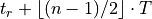 if is odd, else
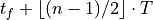
The three indices define the generated clock as follows:
edges[0]: time of the generated clock’s first rising edgeedges[1]: time of the generated clock’s first falling edgeedges[2]: time of the generated clock’s second rising edge (determines the period)
The generated clock period is
time(edges[2]) - time(edges[0]).Indices must be strictly increasing positive integers.
Required: No (Must use one of
-divide_by,-multiply_by,-edges,-phase, or-offset)Note
-edgescannot be combined with-divide_by,-multiply_by,-invert,-phase, or-offset.
- -edge_shift <shift_list>
Specifies a per-edge time offset (in the same units as the master clock period, typically nanoseconds) applied to each of the three edges defined by
-edges. The list must contain exactly three values corresponding positionally to the three edge indices. Positive values shift an edge later in time; negative values shift it earlier.This can be used to model phase offsets or asymmetric duty cycle adjustments that cannot be expressed by
-edgesalone.Required: No
Note
-edge_shiftrequires-edgesto also be specified.
- -phase <float>
Shifts all edges of the generated clock waveform by a fixed phase expressed in degrees relative to the master clock period. Positive values shift edges later in time.
For example,
-phase 90on a 10 ns master clock shifts both the rising and falling edges by .
.When used alone (without
-divide_byor-multiply_by), the generated clock has the same period and duty cycle as the master; only the waveform position is shifted. When combined with-divide_byor-multiply_by, the phase shift is applied after the period scaling.-phaseand-offsetare mutually exclusive.Required: No (Must use one of
-divide_by,-multiply_by,-edges,-phase, or-offset)Note
-phasecannot be combined with-edges.
- -offset <float>
Shifts all edges of the generated clock waveform by a fixed time in nanoseconds. Positive values shift edges later in time.
For example,
-offset 2.0shifts both the rising and falling edges of the generated clock by 2 ns regardless of the clock period.When used alone (without
-divide_byor-multiply_by), the generated clock has the same period and duty cycle as the master; only the waveform position is shifted. When combined with-divide_byor-multiply_by, the offset is applied after the period scaling.-phaseand-offsetare mutually exclusive.Required: No (Must use one of
-divide_by,-multiply_by,-edges,-phase, or-offset)Note
-offsetcannot be combined with-edges.
- -add
Adds a new generated clock definition on a target pin that already has a generated clock. This is used to associate multiple generated clocks with the same target, for example when the source pin carries physically-exclusive clocks (defined with
create_clock-add) and each one produces a separately-named generated clock on the same output.-nameis required when using-addto distinguish each generated clock on the same target.-adddoes not implicitly make the clocks asynchronous or exclusive. Useset_clock_groupsto specify the relationship between the generated clocks.Required: No
- -master_clock <clock_name>
Specifies which master clock domain the generated clock is derived from when the
-sourcepin carries multiple clock domains (i.e. whencreate_clock-addwas used on that pin).Without
-master_clock, VPR requires the source pin to have exactly one clock domain. When the source has multiple domains,-master_clockmust be provided to disambiguate which one this generated clock tracks.The value must be the name of a clock previously defined with
create_clock, and it must originate at the same pin specified by-source.Required: No (Required when the source pin carries more than one clock domain)
- <pin_list>
Specifies the netlist pins or ports where the generated clock is defined.
If none are specified, this is assumed to be a virtual clock.
Required: No
Note
For routed clocks, the timing analysis of a generated clock currently only accounts for routing delay from the generated clock’s source pin to the destination flip-flop clock pin. The routing delay from the master clock’s source pin to the generated clock’s source pin is not yet included.
set_clock_groups
Specifies the relationship between groups of clocks. May be used with netlist or virtual clocks in any combination.
A set_clock_groups constraint disables timing analysis between each clock in one group and each clock in another, making it equivalent to a bidirectional set_false_path for each cross-group clock pair.
For example, the following sets of commands are equivalent:
#Do not analyze any timing paths between clk and clk2, or between
#clk and clk3
set_clock_groups -asynchronous -group {clk} -group {clk2 clk3}
and
set_false_path -from [get_clocks {clk}] -to [get_clocks {clk2 clk3}]
set_false_path -from [get_clocks {clk2 clk3}] -to [get_clocks {clk}]
- set_clock_groups
- -asynchronous
Indicates that the clocks in different groups have no defined phase relationship and paths between them should not be analyzed. Use this when clocks coexist in the design but are driven by independent sources.
Required: Yes (one of
-asynchronous,-physically_exclusive, or-logically_exclusive)Note
The older
-exclusiveoption is a deprecated alias for-asynchronous. It is still accepted but a deprecation warning is produced; use-asynchronousinstead.
- -physically_exclusive
Indicates that only one clock in each group can exist in the design at a time (e.g. a board-level mux selects among several clock sources). Paths between groups are not analyzed.
Required: Yes (one of
-asynchronous,-physically_exclusive, or-logically_exclusive)
- -logically_exclusive
Indicates that an internal mux selects among the clocks, so paths between groups are false paths. Both clock trees are physically present simultaneously. Paths between groups are not analyzed.
Required: Yes (one of
-asynchronous,-physically_exclusive, or-logically_exclusive)
Note
The three relationship types differ in whether signal-integrity (SI) / crosstalk analysis applies between groups:
-physically_exclusiveimplies no SI (clocks never coexist), while-logically_exclusiveand-asynchronousmay have SI because both clock trees are simultaneously present. VPR does not model SI, so all three types are treated identically; timing analysis is disabled between every pair of clocks in different groups.- -group {<clock list or regexes>}
Specifies a group of clocks.
Note
At least 2 groups must be specified.
Required: Yes
set_false_path
Cuts timing paths unidirectionally from each clock in -from to each clock in –to.
Otherwise equivalent to set_clock_groups.
Example Usage:
#Do not analyze paths launched from clk and captured by clk2 or clk3
set_false_path -from [get_clocks {clk}] -to [get_clocks {clk2 clk3}]

#Do not analyze paths launched from clk2 or clk3 and captured by clk
set_false_path -from [get_clocks {clk2 clk3}] -to [get_clocks {clk}]
Note
False paths are supported between entire clock domains, but not between individual registers.
set_max_delay/set_min_delay
Overrides the default setup (max) or hold (min) timing constraint calculated using the information from create_clock with a user-specified delay.
Example Usage:
#Specify a maximum delay of 17 from input_clk to output_clk
set_max_delay 17 -from [get_clocks {input_clk}] -to [get_clocks {output_clk}]

#Specify a minimum delay of 2 from input_clk to output_clk
set_min_delay 2 -from [get_clocks {input_clk}] -to [get_clocks {output_clk}]
Note
Max/Min delays are supported between entire clock domains, but not between individual netlist elements.
- set_max_delay/set_min_delay
- <delay>
The delay value to apply.
Required: Yes
- -from [get_clocks <clock list or regexes>]
Specifies the source clock domain(s).
Required: No
Default: All clocks
- -to [get_clocks <clock list or regexes>]
Specifies the sink clock domain(s).
Required: No
Default: All clocks
set_multicycle_path
Sets how many clock cycles elapse between the launch and capture edges for setup and hold checks.
The default the setup mutlicycle value is 1 (i.e. the capture setup check is performed against the edge one cycle after the launch edge).
The default hold multicycle is one less than the setup multicycle path (e.g. the capture hold check occurs in the same cycle as the launch edge for the default setup multicycle).
Example Usage:
#Create a 4 cycle setup check, and 0 cycle hold check from clkA to clkB
set_multicycle_path -from [get_clocks {clkA}] -to [get_clocks {clkB}] 4

#Create a 3 cycle setup check from clk to clk2
# Note that this moves the default hold check to be 2 cycles
set_multicycle_path -setup -from [get_clocks {clk}] -to [get_clocks {clk2}] 3

#Create a 0 cycle hold check from clk to clk2
# Note that this moves the default hold check back to it's original
# position before the previous setup setup_multicycle_path was applied
set_multicycle_path -hold -from [get_clocks {clk}] -to [get_clocks {clk2}] 2

#Create a multicycle to a specific pin
set_multicycle_path -to [get_pins {my_inst.in\[0\]}] 2
Note
Multicycles are supported between entire clock domains, and ending at specific registers.
- set_multicycle_path
- -setup
Indicates that the multicycle-path applies to setup analysis.
Required: No
- -hold
Indicates that the multicycle-path applies to hold analysis.
Required: No
- -from [get_clocks <clock list or regexes>]
Specifies the source clock domain(s).
Required: No
Default: All clocks
- -to [get_clocks <clock list or regexes>]
Specifies the sink clock domain(s).
Required: No
Default: All clocks
- -to [get_pins <pin list or regexes>]
Specifies the sink/capture netlist pins to which the multicycle is applied.
See also
VPR’s pin naming convention.
Required: No
- <path_multiplier>
The number of cycles that apply to the specified path(s).
Required: Yes
Note
If neither -setup nor -hold the setup multicycle is set to path_multiplier and the hold multicycle offset to 0.
Note
Only a single -to option can be specified (either clocks or pins, but not both).
set_input_delay/set_output_delay
Use set_input_delay if you want timing paths from input I/Os analyzed, and set_output_delay if you want timing paths to output I/Os analyzed.
Note
If these commands are not specified in your SDC, paths from and to I/Os will not be timing analyzed.
These commands constrain each I/O pad specified after get_ports to be timing-equivalent to a register clocked on the clock specified after -clock.
This can be either a clock signal in your design or a virtual clock that does not exist in the design but which is used only to specify the timing of I/Os.
The specified delays are added to I/O timing paths and can be used to model board level delays.
For single-clock circuits, -clock can be wildcarded using * to refer to the single netlist clock, although this is not supported in standard SDC.
This allows a single SDC command to constrain I/Os in all single-clock circuits.
Example Usage:
#Set a maximum input delay of 0.5 (relative to input_clk) on
#ports in1, in2 and in3
set_input_delay -clock input_clk -max 0.5 [get_ports {in1 in2 in3}]

#Set a minimum output delay of 1.0 (relative to output_clk) on
#all ports matching starting with 'out*'
set_output_delay -clock output_clk -min 1 [get_ports {out*}]

#Set both the maximum and minimum output delay to 0.3 for all I/Os
#in the design
set_output_delay -clock clk2 0.3 [get_ports {*}]
- set_input_delay/set_output_delay
- -clock <virtual or netlist clock>
Specifies the virtual or netlist clock the delay is relative to.
Required: Yes
- -max
Specifies that the delay value should be treated as the maximum delay.
Required: No
- -min
Specifies that the delay value should be treated as the minimum delay.
Required: No
- <delay>
Specifies the delay value to be applied
Required: Yes
- [get_ports {<I/O list or regexes>}]
Specifies the port names or port name regex.
Required: Yes
Note
If neither
-minnor-maxare specified the delay value is applied to both.
set_clock_uncertainty
Sets the clock uncertainty between clock domains. This is typically used to model uncertainty in the clock arrival times due to clock jitter.
Example Usage:
#Sets the clock uncertainty between all clock domain pairs to 0.025
set_clock_uncertainty 0.025

#Sets the clock uncertainty from 'clk' to all other clock domains to 0.05
set_clock_uncertainty -from [get_clocks {clk}] 0.05

#Sets the clock uncertainty from 'clk' to 'clk2' to 0.75
set_clock_uncertainty -from [get_clocks {clk}]  -to [get_clocks {clk2}] 0.75
- set_clock_uncertainty
- -from [get_clocks <clock list or regexes>]
Specifies the source clock domain(s).
Required: No
Default: All clocks
- -to [get_clocks <clock list or regexes>]
Specifies the sink clock domain(s).
Required: No
Default: All clocks
- -setup
Specifies the clock uncertainty for setup analysis.
Required: No
- -hold
Specifies the clock uncertainty for hold analysis.
Required: No
- <uncertainty>
The clock uncertainty value between the from and to clocks.
Required: Yes
Note
If neither
-setupnor-holdare specified the uncertainty value is applied to both.
set_clock_latency
Sets the latency of a clock. VPR automatically calculates on-chip clock network delay, and so only source latency is supported.
Source clock latency corresponds to the delay from the true clock source (e.g. off-chip clock generator) to the on-chip clock definition point.
#Sets the source clock latency of 'clk' to 1.0
set_clock_latency -source 1.0 [get_clocks {clk}]
- set_clock_latency
- -source
Specifies that the latency is the source latency.
Required: Yes
- -early
Specifies that the latency applies to early paths.
Required: No
- -late
Specifies that the latency applies to late paths.
Required: No
- <latency>
The clock’s latency.
Required: Yes
- [get_clocks <clock list or regexes>]
Specifies the clock domain(s).
Required: Yes
Note
If neither
-earlynor-lateare specified the latency value is applied to both.
set_disable_timing
Disables timing between a pair of connected pins in the netlist. This is typically used to manually break combinational loops.
#Disables the timing edge between the pins 'FFA.Q[0]' and 'to_FFD.in[0]' on
set_disable_timing -from [get_pins {FFA.Q[0]}] -to [get_pins {to_FFD.in[0]}]
- set_disable_timing
- -from [get_pins <pin list or regexes>]
Specifies the source netlist pins.
See also
VPR’s pin naming convention.
Required: Yes
- -to [get_pins <pin list or regexes>]
Specifies the sink netlist pins.
See also
VPR’s pin naming convention.
Required: Yes
Note
Make sure to escape the characters in the regexes.
Special Characters
- # (comment), \ (line continued), * (wildcard), {} (string escape)
#starts a comment – everything remaining on this line will be ignored.\at the end of a line indicates that a command wraps to the next line.*is used in aget_clocks/get_portscommand or at the end ofcreate_clockto match all netlist clocks. Partial wildcarding (e.g.clk*to matchclkandclk2) is also supported. As mentioned above,*can be used in set_input_delay and set_output delay to refer to the netlist clock for single-clock circuits only, although this is not supported in standard SDC.{}escapes strings, e.g.{top^clk}matches a clock calledtop^clk, whiletop^clkwithout braces gives an error because of the special^character.
SDC Examples
The following are sample SDC files for common non-default cases (assuming netlist clock domains clk and clk2).
A
Cut I/Os and analyse only register-to-register paths, including paths between clock domains; optimize to run as fast as possible.
create_clock -period 0 *
B
Same as A, but with paths between clock domains cut. Separate target frequencies are specified.
create_clock -period 2 clk
create_clock -period 3 clk2
set_clock_groups -asynchronous -group {clk} -group {clk2}
C
Same as B, but with paths to and from I/Os now analyzed. This is the same as the multi-clock default, but with custom period constraints.
create_clock -period 2 clk
create_clock -period 3 clk2
create_clock -period 3.5 -name virtual_io_clock
set_clock_groups -asynchronous -group {clk} -group {clk2}
set_input_delay -clock virtual_io_clock -max 0 [get_ports {*}]
set_output_delay -clock virtual_io_clock -max 0 [get_ports {*}]
D
Changing the phase between clocks, and accounting for delay through I/Os with set_input/output delay constraints.
#Custom waveform rising edge at 1.25, falling at 2.75
create_clock -period 3 -waveform {1.25 2.75} clk
create_clock -period 2 clk2
create_clock -period 2.5 -name virtual_io_clock
set_input_delay -clock virtual_io_clock -max 1 [get_ports {*}]
set_output_delay -clock virtual_io_clock -max 0.5 [get_ports {*}]
E
Sample using many supported SDC commands. Inputs and outputs are constrained on separate virtual clocks.
create_clock -period 3 -waveform {1.25 2.75} clk
create_clock -period 2 clk2
create_clock -period 1 -name input_clk
create_clock -period 0 -name output_clk
set_clock_groups -asynchronous -group input_clk -group clk2
set_false_path -from [get_clocks {clk}] -to [get_clocks {output_clk}]
set_max_delay 17 -from [get_clocks {input_clk}] -to [get_clocks {output_clk}]
set_multicycle_path -setup -from [get_clocks {clk}] -to [get_clocks {clk2}] 3
set_input_delay -clock input_clk -max 0.5 [get_ports {in1 in2 in3}]
set_output_delay -clock output_clk -max 1 [get_ports {out*}]
F
Sample using all remaining SDC commands.
create_clock -period 3 -waveform {1.25 2.75} clk
create_clock -period 2 clk2
create_clock -period 1 -name input_clk
create_clock -period 0 -name output_clk
set_clock_latency -source 1.0 [get_clocks{clk}]
#if neither early nor late is specified then the latency applies to early paths
set_clock_groups -asynchronous -group input_clk -group clk2
set_false_path -from [get_clocks{clk}] -to [get_clocks{output_clk}]
set_input_delay -clock input_clk -max 0.5 [get_ports{in1 in2 in3}]
set_output_delay -clock output_clk -min 1 [get_ports{out*}]
set_max_delay 17 -from [get_clocks{input_clk}] -to [get_clocks{output_clk}]
set_min_delay 2 -from [get_clocks{input_clk}] -to [get_clocks{output_clk}]
set_multicycle_path -setup -from [get_clocks{clk}] -to [get_clocks{clk2}] 3
#For multicycle_path, if setup is specified then hold is also implicitly specified
set_clock_uncertainty -from [get_clocks{clk}] -to [get_clocks{clk2}] 0.75
#For set_clock_uncertainty, if neither setup nor hold is unspecified then uncertainty is applied to both
set_disable_timing -from [get_pins {FFA.Q[0]}] -to [get_pins {to_FFD.in[0]}]