Placement Constraints
VPR supports running flows with placement constraints. Placement constraints are set on primitives to lock them down to specified regions on the FPGA chip. For example, a user may use placement constraints to lock down pins to specific locations on the chip. Also, groups of primitives may be locked down to regions on the chip in CAD flows that use floorplanning or modular design, or to hand-place a timing critical piece.
The placement constraints should be specified by the user using an XML constraints file format, as described in the section below. When VPR is run with placement constraints, both the packing and placement flows are performed in such a way that the constraints are respected. The packing stage does not pack any primitives together that have conflicting floorplan constraints, and can optionally pin atoms to specific locations inside a clustered logic block (see logical_block_location below). The placement stage considers the floorplan constraints when choosing a location for each clustered block during initial placement, and does not move any block outside of its constraint boundaries during place moves.
A Placement Constraints File Example
 1<vpr_constraints tool_name="vpr">
 2        <partition_list>
 3                <partition name="Part0">
 4                                <add_atom name_pattern="li354"/>
 5                                <add_atom name_pattern="alu.*" is_regex="true"/> <!-- Regular expressions can be used to provide name patterns of the primitives to be added -->
 6                                <add_atom name_pattern="n877"/>
 7                                <add_region x_low="3" y_low="1" x_high="7" y_high="2"/> <!-- Two rectangular regions are specified, together describing an L-shaped region -->
 8                                <add_region x_low="7" y_low="3" x_high="7" y_high="6"/>
 9                                <add_logical_block name_pattern="clbA"/> <!-- Constrain atoms to clbA logical block type -->
10                </partition>
11                <partition name="Part1">
12                                <add_region x_low="3" y_low="7" x_high="3" y_high="7" subtile="0"/> <!-- One specific location is specified -->
13                                <add_atom name_pattern="n4917"/>
14                                <add_atom name_pattern="n6010"/>
15                </partition>
16
17                <partition name="Part2">
18                                <add_region x_low="3" y_low="3" x_high="85" y_high="85"/> <!-- When the layer is not explicitly specified, layer 0 is assumed. -->
19                                <add_region x_low="8" y_low="5" x_high="142" y_high="29" layer_low="0" layer_high="1"/> <!-- In 3D architectures, the region can span across multiple layers. -->
20                                <add_region x_low="6" y_low="55" x_high="50" y_high="129" layer_low="2" layer_high="2"/> <!-- If the region only covers a non-zero layer, both layer_low and layer_high must be set the same value. -->
21                                <add_atom name_pattern="n135"/>
22                                <add_atom name_pattern="n7016"/>
23                </partition>
24        </partition_list>
25</vpr_constraints>
Placement Constraints File Format
VPR has a specific XML format which must be used when creating a placement constraints file. The purpose of this constraints file is to specify
Which primitives are to have placement constraints
The regions on the FPGA chip to which those primitives must be constrained
Which logical block types the primitives can be mapped to (optional)
The file is passed as an input to VPR when running with placement constraints. When the file is read in, its information is used during the packing and placement stages of VPR. The hierarchy of the file is set up as follows.
The top level tag is the <vpr_constraints> tag. This tag can contain one <partition_list> tag. The <partition_list> tag can be made up of an unbounded number of <partition> tags. The <partition> tags contains all of the detailed information of the placement constraints, and is described in detail below.
Partitions, Atoms, Regions, and Logical Block Types
- <partition name="string">" title="Link to this definition">
A partition is made up of three components - a group of primitives (a.k.a. atoms) that must be constrained to the same area on the chip, a set of one or more regions specifying where those primitives must be constrained, and optionally a set of logical block types that those primitives can be mapped to. The information for each partition is contained within a
<partition>tag, and the number ofpartitiontags that the partition_list tag can contain is unbounded.- Required Attributes:
name – A name for the partition.
- <add_atom name_pattern="string">" title="Link to this definition">
An
<add_atom>tag is used to add an atom that must be constrained to the partition. Each partition can contain any number of atoms from the circuit. The<add_atom>tag has the following attribute:- Required Attributes:
name_pattern –
The name of the atom which can be the exact name of an atom from the input atom netlist passed to VPR, or a regular expression pattern matching one or more atom names. By default, name_pattern is treated as an exact atom name. If
is_regexis set tofalseor not provided, VPR will only attempt to find an exact match. If no match is found, the constraint will be ignored and a warning will be printed. Ifis_regexis set totrue, VPR will search for all atoms whose names match the regex pattern provided. If no matches are found, the constraint will be ignored and a warning will be printed.For example, to add all atoms
alu[0],alu[1], andalu[2]to the partitionPart0, the user can usealu.*as thename_patternand setis_regex="true"in the<add_atom>tag.
- Optional Attributes:
is_regex – A boolean value indicating whether the
name_patternshould be treated as a regular expression. Default:falselogical_block_location – Constrains the atom to a specified location inside a logic block during packing. See Logical Block Location for syntax, examples, and figures.
An
<add_region>tag is used to add a region to the partition. Aregionis a rectangular area or cubic volume on the chip. A partition can contain any number of independent regions - the regions within one partition must not overlap with each other (in order to ease processing when loading in the file). An<add_region>tag has the following attributes.- Required Attributes:
x_low – The x value of the lower left point of the rectangle.
y_low – The y value of the lower left point of the rectangle.
x_high – The x value of the upper right point of the rectangle.
y_high – The y value of the upper right point of the rectangle.
- Optional Attributes:
subtile – Each x, y location on the grid may contain multiple locations known as subtiles. This parameter is an optional value specifying the subtile location that the atom(s) of the partition shall be constrained to. This attribute is commonly used when constraining an atom to a specific location on the chip (e.g. an exact I/O location). It is legal to use with larger regions, but uncommon.
layer_low – The lowest layer number that the region covers. Default:
0layer_high – The highest layer number that the region covers. Default:
0
In 2D architectures,
layer_lowandlayer_highcan be safely ignored as their default value is 0. In 3D architectures, a region can span across multiple layers or be assigned to a specific layer. For assigning a region to a specific non-zero layer, the user should set bothlayer_lowandlayer_highto the desired layer number. If a layer range is to be covered by the region, the user setlayer_lowandlayer_highto different values.If a user would like to specify an area on the chip with an unusual shape (e.g. L-shaped or T-shaped), they can simply add multiple
<add_region>tags to cover the area specified.It is strongly recommended that different partitions do not overlap. The packing algorithm compares the number of clustered blocks and the number of physical blocks in a region to decide if it should pack atoms inside a partition more aggressively when there are not enough resources in a partition. Overlapping partitions cause some physical blocks to be counted in more than one partition, which will degrade the packing algorithm’s ability to create a clustering that can be placed given the floorplan constraints.
- <add_logical_block name_pattern="string">" title="Link to this definition">
An
<add_logical_block>tag is used to constrain the atoms in the partition to specific logical block types. This tag is optional and can be repeated multiple times within a partition to specify multiple allowed logical block types. When logical block type constraints are specified, atoms in the partition will only be packed into clusters of the specified logical block types.Logical blocks are the types of complex blocks found in the FPGA architecture. They are defined as top-level
pb_typeelements in the complex block list of the architecture description file and correspond to the equivalent sites available in sub-tiles across the chip.The
<add_logical_block>tag has the following attribute:- Required Attributes:
name_pattern – The name of the logical block type that atoms in this partition are allowed to be mapped to. This can be the exact name of a logical block type from the device architecture, or a regular expression pattern matching one or more logical block type names. If
is_regexis set tofalseor not provided, VPR will only attempt to find an exact match. If no match is found, the<add_logical_block>tag will be ignored and a warning will be printed. Ifis_regexis set totrue, VPR will search for all logical blocks whose names match the regex pattern provided. If no matches are found, the<add_logical_block>tag will be ignored and a warning will be printed. For example, to constrain atoms to bothclbAandclbBlogical block types, the user can add two<add_logical_block>tags withname_patternvalues ofclbAandclbBrespectively, or use a single tag withname_pattern="clb[AB]".
- Optional Attributes:
is_regex – A boolean value indicating whether the
name_patternshould be treated as a regular expression. Default:false
Use Case Example: Architectures such as Stratix-IV contain multiple types of RAM blocks (e.g., M9K and M144K). This tag can be used to constrain certain RAM slices to specific RAM logical block types. For instance, if certain memory operations require the larger M144K blocks, you can add
<add_logical_block name_pattern="M144K"/>to ensure those atoms are mapped only to the appropriate RAM block type.Note: If no
<add_logical_block>tags are specified for a partition, atoms in the partition are not constrained to any particular logical block type and can be mapped to any available type.
Logical Block Location
Some designs must place primitives at fixed FPGA sites and at fixed slices inside a logic block, for example to meet timing to an external interface (Fig. 69).
In each <partition>, use:
<add_region>— which logic block site on the chip (x_low,y_low, …).logical_block_locationon<add_atom>— which slice inside that block (from the architecturepb_typehierarchy).
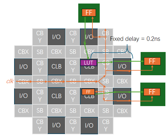
Fig. 69 FPGA floorplan: interfacing atoms (LUT and FF) are constrained to specific CLB sites and connected to external logic.
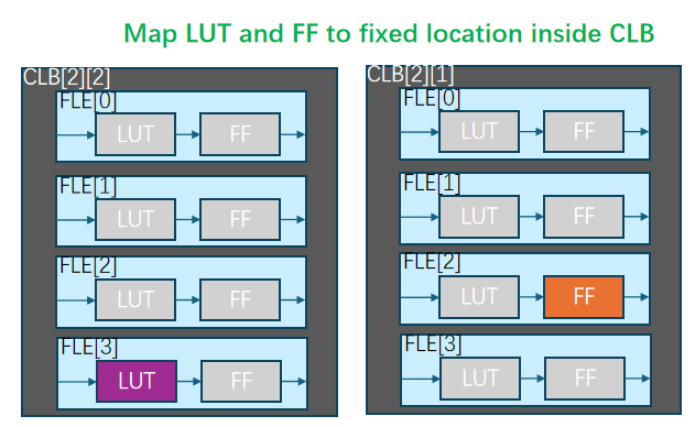
Fig. 70 For each CLB placed by add_region, logical_block_location picks the slice inside it—for example,
CLB at (2, 1): FLE 2 and an FF; CLB at (2, 2): FLE 3 and a LUT.
Note
The first level (e.g. clb) may omit the index: clb.fle[0]... is equivalent to clb[0].fle[0]....
Deeper levels should include indices when you need a specific slice.
Example:
<partition name="fix_ff_atom_d">
        <add_atom name_pattern="d" logical_block_location="clb[0].fle[2]{n1_lut4}.ble4[0].ff[0]"/>
        <add_region x_low="2" y_low="1" x_high="2" y_high="1"/>
</partition>
<partition name="fix_lut_atom_c">
        <add_atom name_pattern="c" logical_block_location="clb[0].fle[3]{n1_lut4}.ble4[0].lut4[0]"/>
        <add_region x_low="2" y_low="2" x_high="2" y_high="2"/>
</partition>